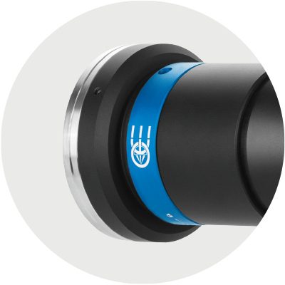
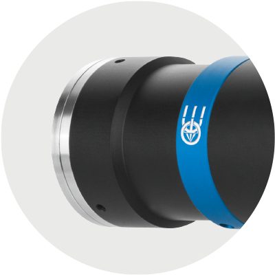
TC4K series
Flat telecentric lenses for 4k line scan sensors
Product range expansion: new M42x1 FD12 mount now available (-J).


Key advantages
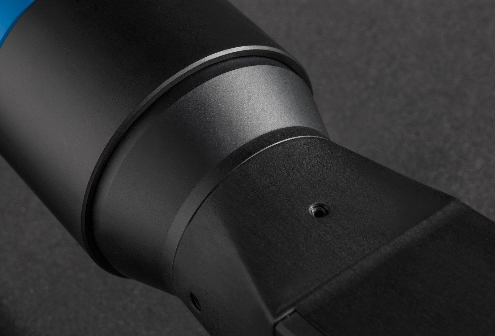
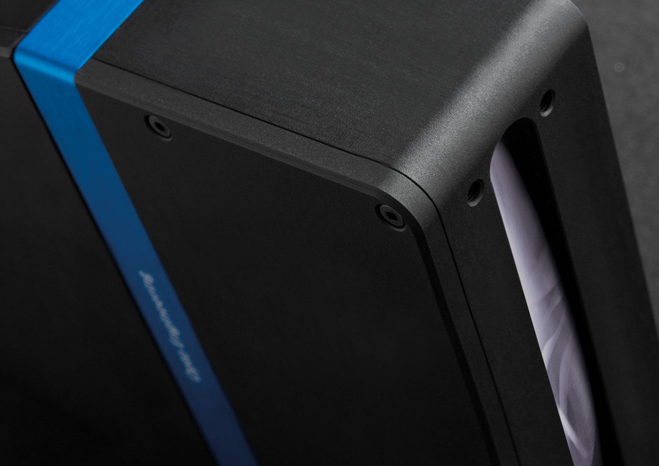
- Compact design
“Flat” shape for easy integration - Easy rotational phase and focus adjustment
Robust and precise tuning of FOV phase angle and best focus position - Compatible LTCL4K telecentric illuminators
with matching flat design. - Dedicated CMMR4K mirrors
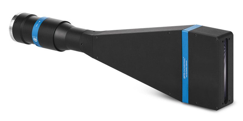
90° right-angled attachment for easy integration in tight spaces. - Detailed test report with measured optical parameters
TC4K series telecentric lenses have been designed for measurement applications using line scan cameras with a detector size up to 28.7 mm (e.g. 4096 pixels with pixel size 7 μm).
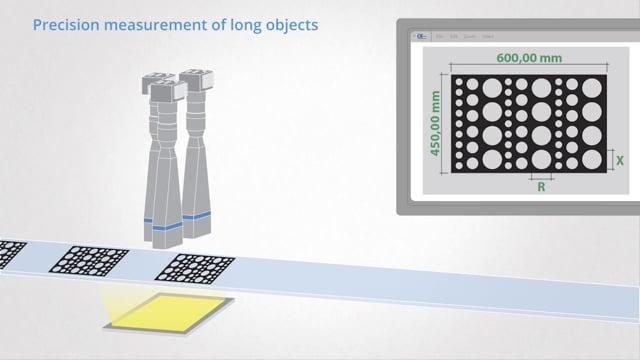
Dimensional constraints are often a major issue when designing image scanning systems where the sample or the camera itself must be moved: TC4K series is the Opto Engineering® solution for applications and machines with tight dimensional constraints. Compatible LTCL4K illuminators with matching flat design and dedicated accessories allow for optical combinations that fit most geometrical measurement configurations.
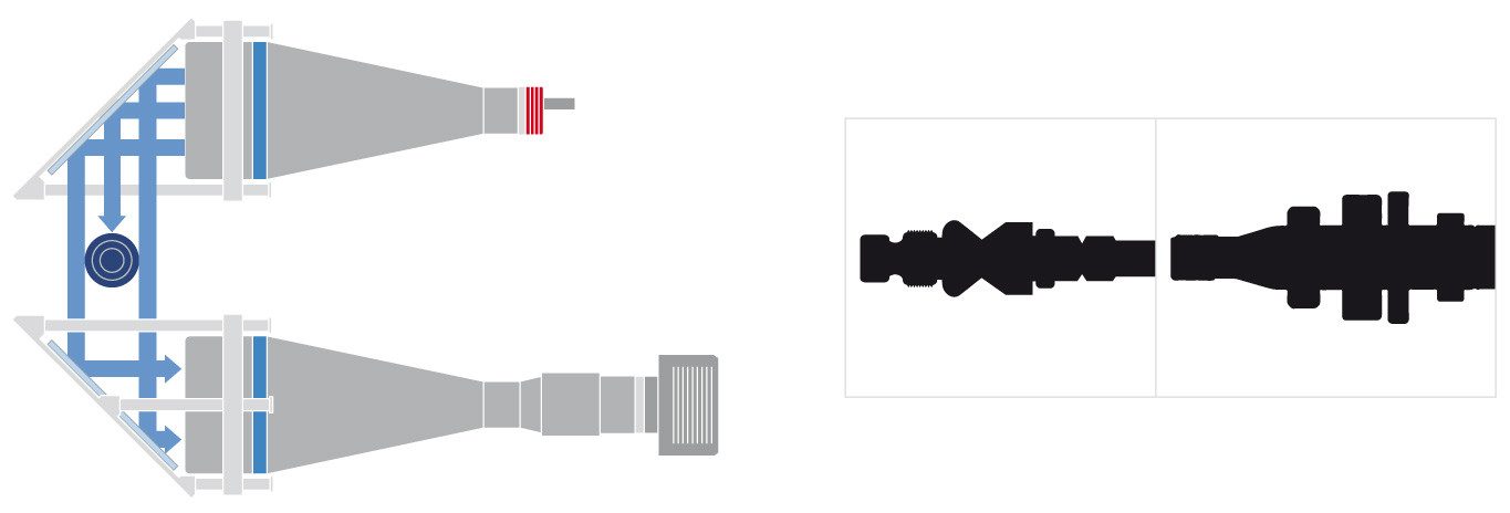
The TC4K series feature standard F or M42 mount to fit common line scan camera interfaces; additional mounts are available upon request. Moreover, the lens-camera interface provides both fine detector phase adjustment and a precise focusing mechanism. Detector phase adjustment allows to precisely position the linear FOV at 90° from the object movement direction.
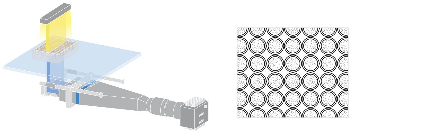
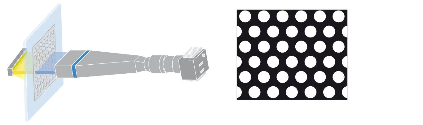
Application examples
Notes
- Working distance: distance between the front end of the mechanics and the object. Set this distance within ±3% of the nominal value for maximum resolution and minimum distortion.
- Working f-number (wf/N): the real f-number of a lens in operating conditions.
- Maximum angle between chief rays and optical axis on the object side. Typical (average production) values and maximum (guaranteed) values are listed.
- Percent deviation of the real image compared to an ideal, undistorted image. Typical (average production) values and maximum (guaranteed) values are listed.
- At the borders of the field depth the image can be still used for measurement but, to get a very sharp image, only half of the nominal field depth should be considered. Pixel size used for calculation is 7 μm.
- Object side, calculated with the Rayleigh criterion with λ= 520 nm
- FD stands for Flange Distance (in mm), defined as the distance from the mounting flange to the camera detector plane.
- Indicates the availability of an integrated camera phase adjustment feature.
- Measured from the front end of the mechanics to the camera flange.
Ordering information
-F for F-mount.
-N for M42x1 mount (flange distance FD 10.56 mm).
For example, TC4K060-N refers to a TC4K060 with M42x1 mount.